| For all you
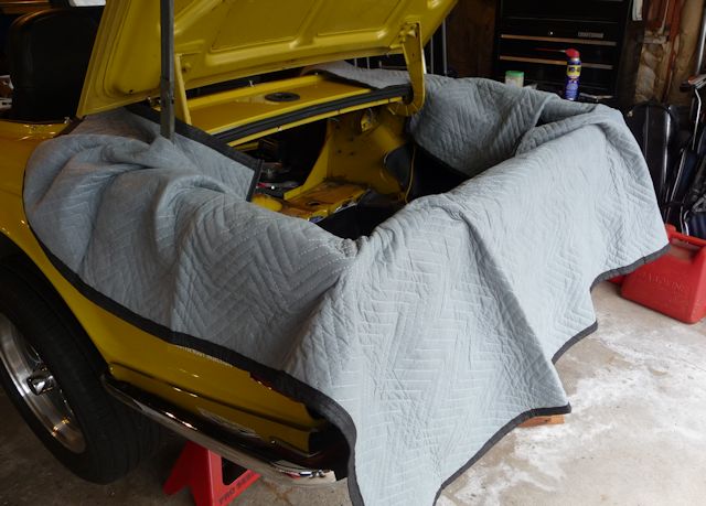
smart guys who bought one of my fender blankets,
you can reverse them to protect the rear of
the car. You'll be installing and pulling
the new tank quite a few times to drill all
the mounting holes. |
 |
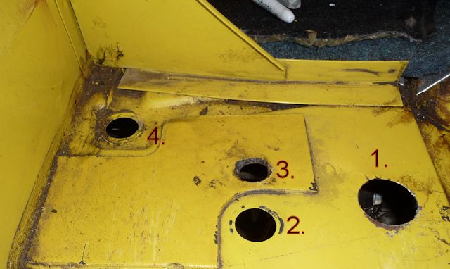
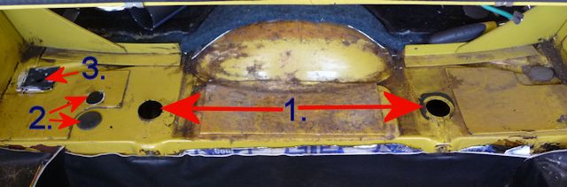
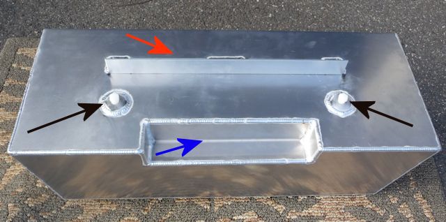
| With the old
tank out, you'll see the following holes: 1 -
tank outlet hole,
2 - evaporative canister return line and 4
will be a plugged hole. Hole #3 is one I put
in for my TBI fuel return line. Hole #1 is
repeated in the right side of the car and
will have to have the plug removed as the
aluminum tank has two outlets. Take the
rubber plug from hole #4 and use it in hole
#2. |
 |
| When the tank
is installed, all you can see is hole #4
which will be used for the Evaporative
canister return line and the fuel return
line for my TBI powered car. |
 |
|
This isn't pretty
and I plan on covering it with another piece
of foam but this is where the return line
and evaporative canister line be routed to
the top of the tank. It's the same foam I
used on the bottom of the tank.
One hole for the
evaporative canister line and one for the
fuel return line. Only TBI/FI cars will have
the return line and the evap line was only
on certain later cars. |
 |
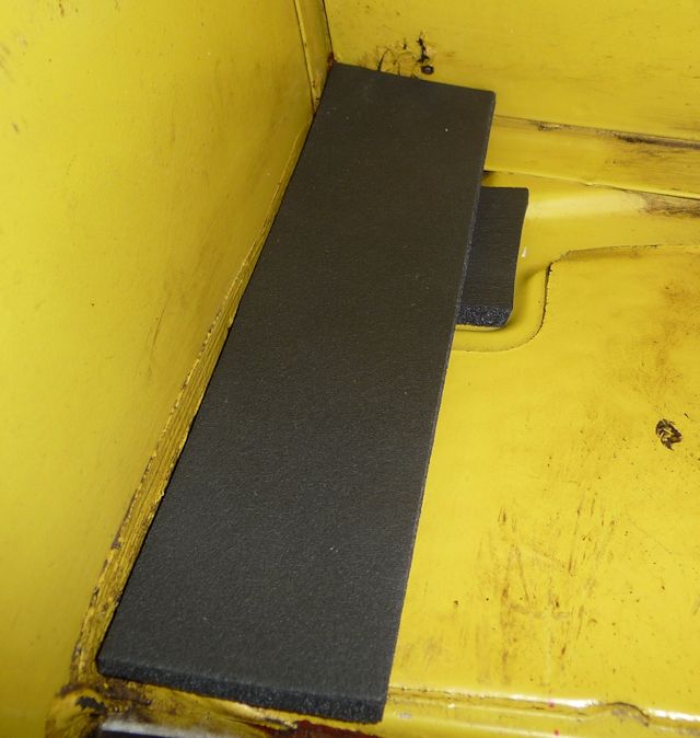
|
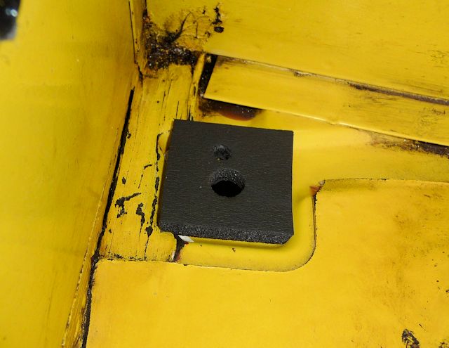
I used another
piece on top of the small square one and
punched matching holes in to it before using
Ultra Black to glue them together. |
 |
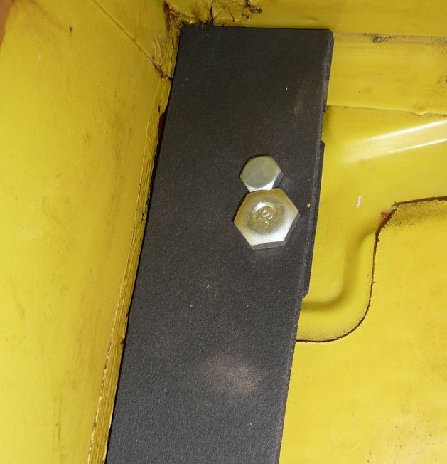
|
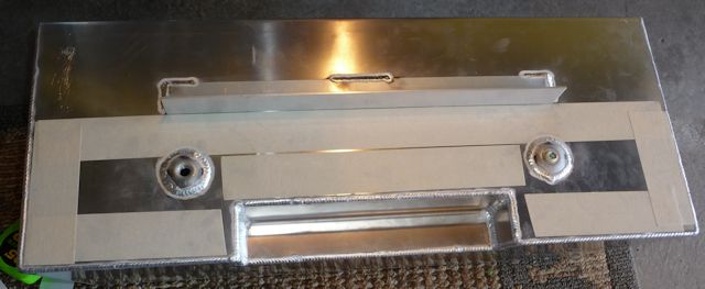
All glued
together and glued to the car with Ultra
Black Sealer. The two bolts were used to
make sure the holes stayed lined up. |
 |
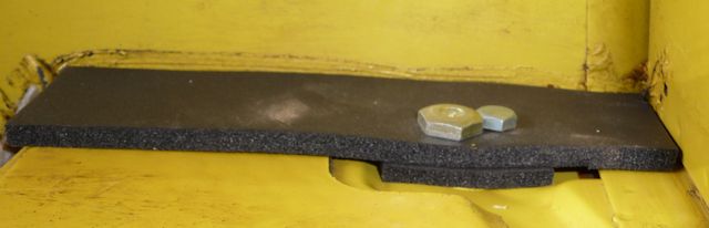
|
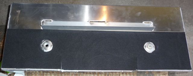
This side view
shows how the two layers fill in the floor
gaps. |
 |
|
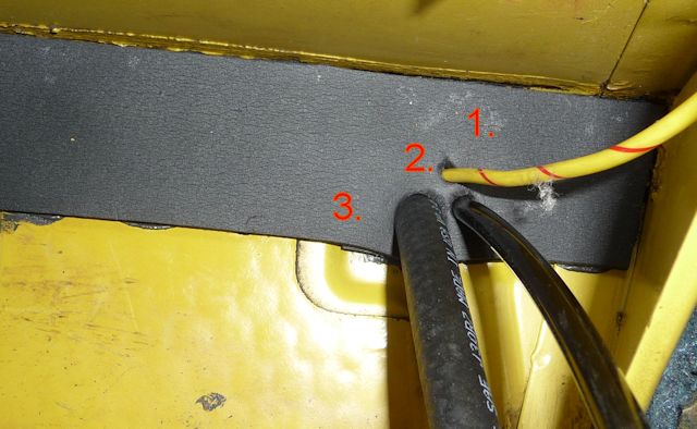
I added another
hole with an awl for the power feed (#1) to
my fuel pump. I'll also squeeze the ground
wire in the same hole. #2 is the line from
the Charcoal Canister and #3 is my fuel
return line. |
 |
|
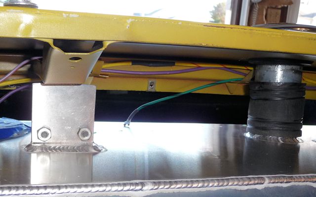
And the tank
snug's right up against the foam. |
 |
|
Here's an overall view.............Holes #1 are unplugged and the outlet bungs
will rest in them. Holes #2 are plugged and
Hole #3 has the foam piece for the return
lines to pass through. |
 |
|
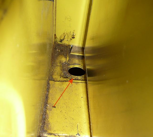
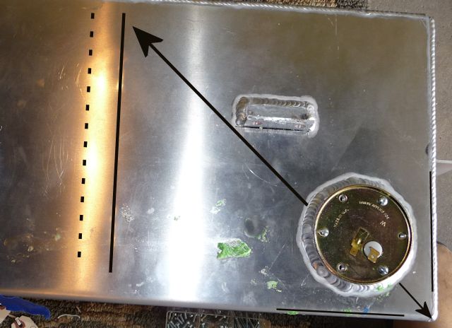
I put the fuel
sender temporarily in place to see how it
fit in the tank and in the car. The sender
goes in on the angle of the arrow and when I
turned the tank upside down I heard it hit
the top of the tank so it should register
Full. However Dave Boyd had to shorten the
arm of the sender by bending it so it
wouldn't hit the baffle (solid line). All
final production tanks will have the baffles
moved in (dotted line) and the sender moved as far
to the back & right as possible. That will
eliminate the need to bend the sender arm. |
 |
|
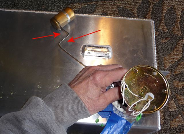
Here you can see how the arm was bent.
Because Dave is replacing this tank with the
production version, I didn't permanently
install the sender. If I had I would have
used Hylomar as the gasket sealer. |
 |
|
Remove the two
white plugs in the outlet holes. |
 |
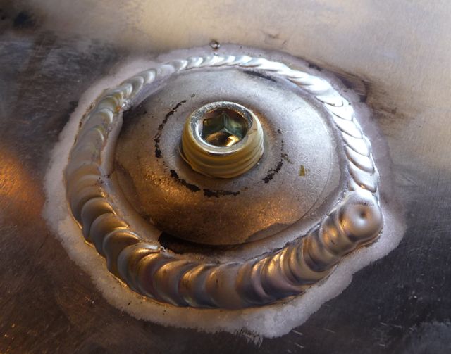
| The tank has
two outlet bungs because some of the more
"spirited" drivers have experienced fuel
starvation with a low tank and aggressive
cornering......especially the guys with Fuel
Injection ot TBI. I've got TBI but drive
like an old lady so I plugged the hole with
a set screw compatible with a 1/4" NPT
fitting. You don't want anything sticking up
more that 1/4" or you may have trouble
getting the tank in as it's a tight fit.
Also...MAKE SURE you use the yellow Teflon
tape rated for gasoline environment. |
 |
| The stock
tank sat on felt which absorbed both gas and
the smell of gas but I wanted something more
modern. First was double sided
tape........... |
 |
| I used an oil
resistant foam from McMaster ( Part#85175K53
) that's 3/16" thick. It also comes in
1/8" and 1/4" but the 1/4" is too thick so
stick with the thinner product. If I were
ordering again I'd go with the 1/8" thick
foam. |
 |
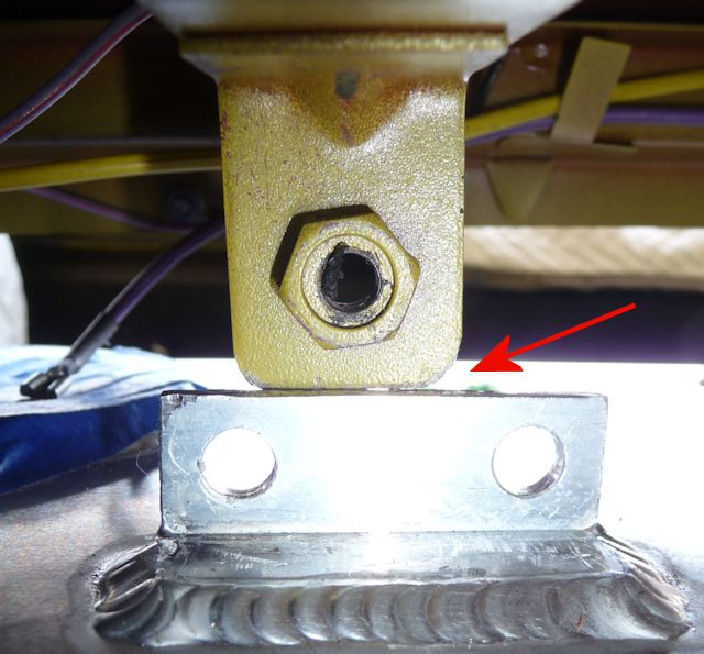
| Every car
will be a little different but here's how it
went with my car........position the tank in
the trunk and tilt it so the return line
fitting clears the top trunk lip. Slide it
under, level and lift the outlet bungs over
the floor. Push the tank back until the
bungs drop in place and the tank side mounts
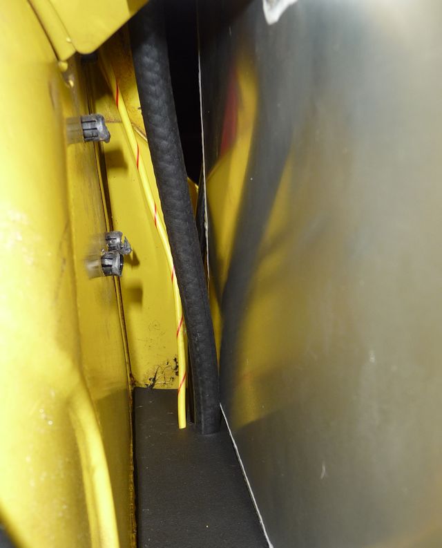
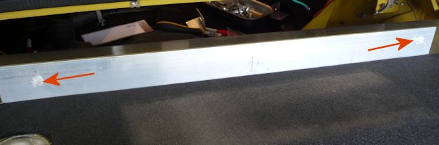
hit the trunk side mounts. I had a slight
interference with the right side top mount
and had to push the tank down into the foam
to get it to clear the top trunk mount. The
left side mount had no problems. Seeing as
the tank measures the same at both mounts,
the issue was with my car. I did some
measuring and found that the right side car
mount was 1/16" lower than the right
side.... just enough to cause some
interference as seen below. |
 |
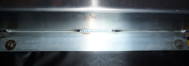
| Before making
this cut, check and see if you can maneuver
the tank into position. If not, or if you
want to make the job easier, it's a simple
cut with a hacksaw that will never be seen
once the trunk panel is in place. |
 |
|
This is the most
important tip........everything
revolves around the filler neck so once the
tank is in place, temporarily install the filler hose
and filler cap. That will ensure all the
mounting points line up. I even used a
little Vaseline on the inside of the
filler hose to let the pieces slide on and
off much easier. Before drilling any
mounting hole I first installed the filler
hose and cap to make sure it was aligned.
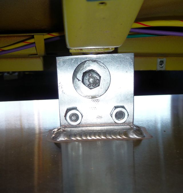
With the tank
in place and wedged up against the side
mounts I took a Sharpie and pushed it
through the nut to mark the side bracket. |
 |
| Make sure you
support all the mounting points before
whacking them with a set punch and drilling
the hole. |
 |
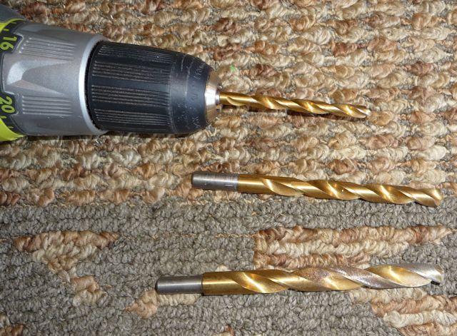
| When using a
hand drill, I'm a fan of "step drilling",
starting with a 1/4" bit then a 3/8" and
finally the 1/2"........ OR............. |
 |
|
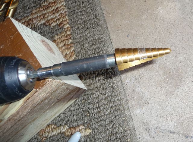
If you have one
of these, do the 1/4" and 3/8" holes and
then step it down to 1/2" |
 |
|
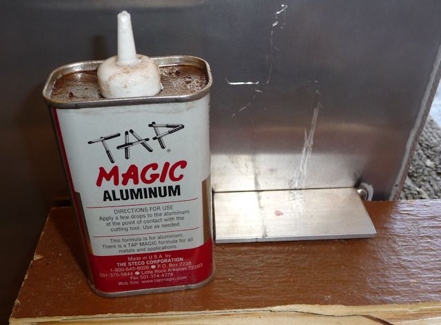
And don't forget
the Tap Magic.... |
 |
| Drilling a
1/2" hole gives just that little extra
"slop" to ensure loosely attaching the tank
and moving it for alignment at all 6
mounting points. |
 |
|
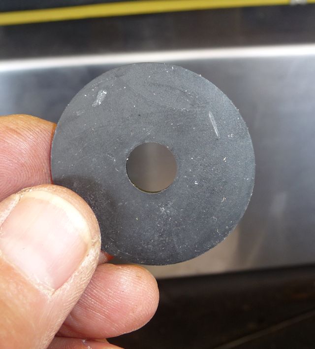
These rubber
washers aren't absolutely necessary but they
sure won't hurt. |
 |
|
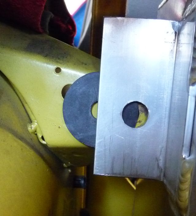
Just slide them
in and tighten. |
 |
| I did the
right side mount, installed the tank and
neck filler and located the left side
mounting hole. Once I had both of those
sides done, I left them finger tight and
moved to the top mounts.
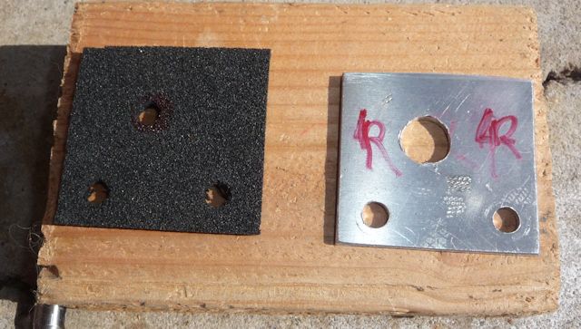
The top mounts
require the use of two small blank plates
that are included with the tank. I had given
Dave a measurement of 2" x 2" but future
ones will be 2" x 1-7/8" as I had to trim
mine to get them to properly fit.
|
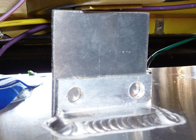 |
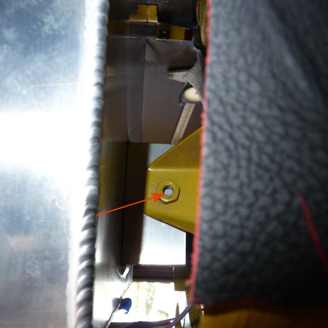
| It was a bit
of a pain but I always worked with the
filler cap and hose in place. The bottom two
holes were marked with a Sharpie and drilled
to 5/16". The bolts are 1/4" X 1" with Nyloc
nuts. Once these were in place I reached
around with my trusty Sharpie and marked the
top hole location. NOTE that the filler
neck is in place before drilling..... the
side mounts are also loosely bolted in
place. |
 |
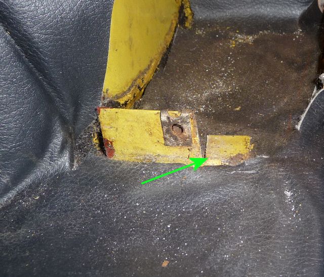
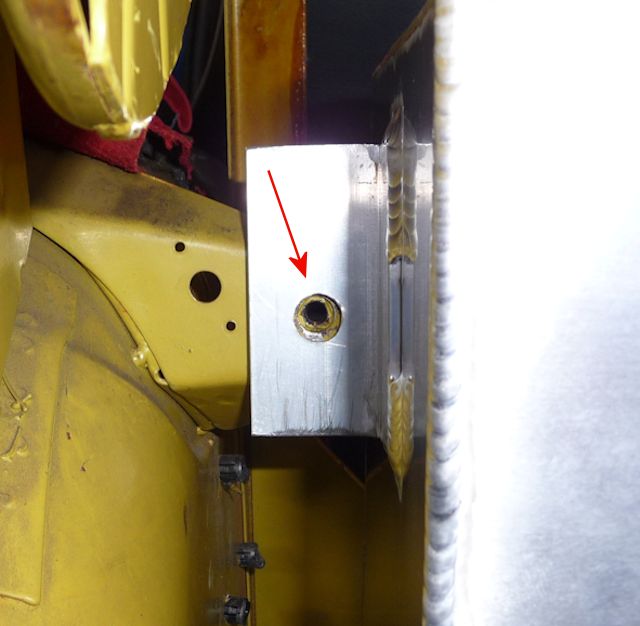
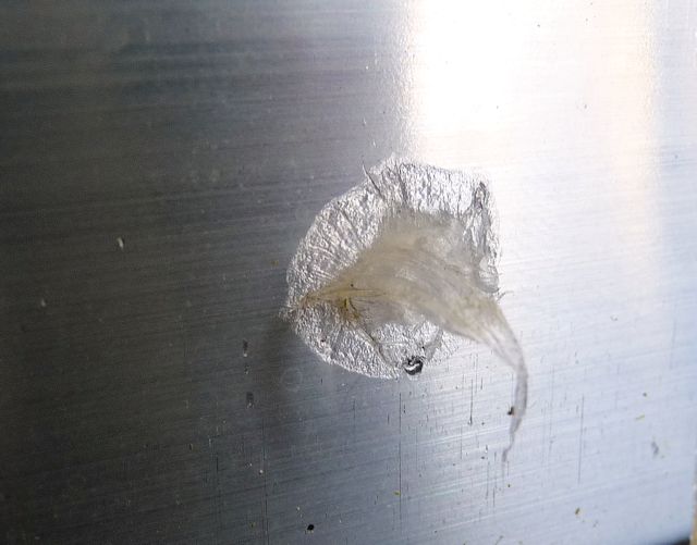
| As luck would
have it, this mounting nut was
stripped.......to the point where a 1/4"
bolt will slide right through to get secured
with a nut. |
 |
|
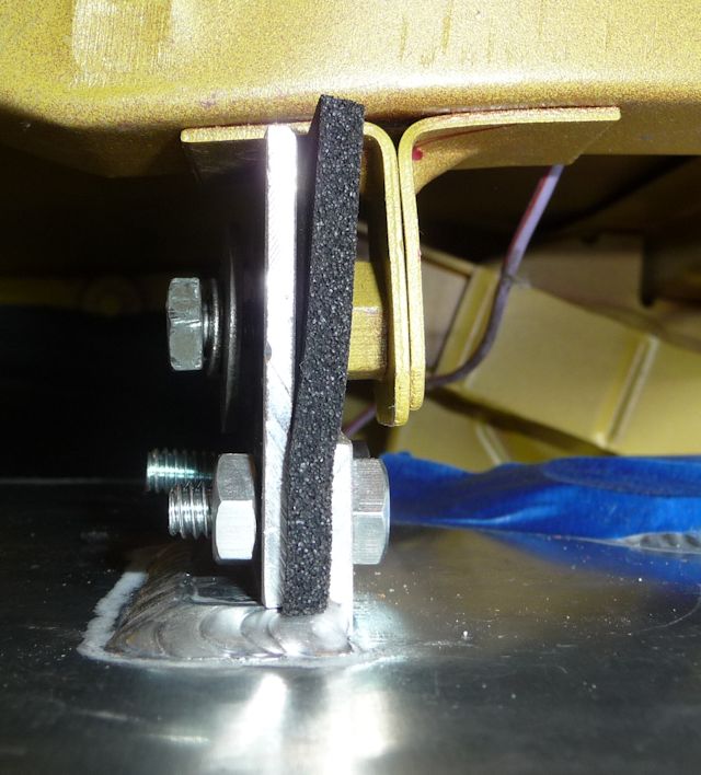
For the top tabs
I used some of the foam that I put on the
bottom of the tank. |
 |
|
All loosely
installed and time to move to the bottom
mounts. |
 |
|
Top and Side mounts are done..........now
the more difficult bottom mounting holes.
Time to visualize as I forgot to take a
picture! Install the two bottom bolts and
leave them about 1/2" shy of being screwed
all the way in. Now slop a glob of Vaseline
on the head of the bolt....... you could
also use some lipstick to transfer the mark.
Now install the tank, carefully lining
everything up and push the tank against the
bolt heads and you'll end up with something
like this. |
 |
|
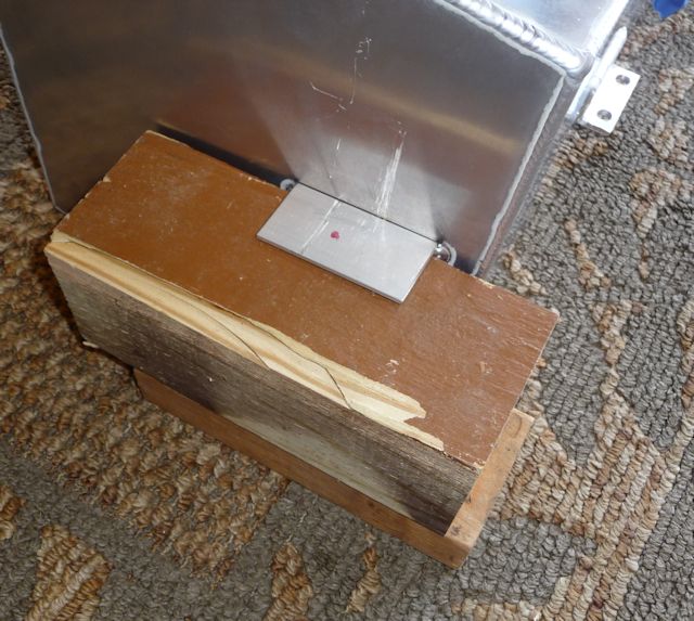
A closer look
makes the location obvious. |
 |
|
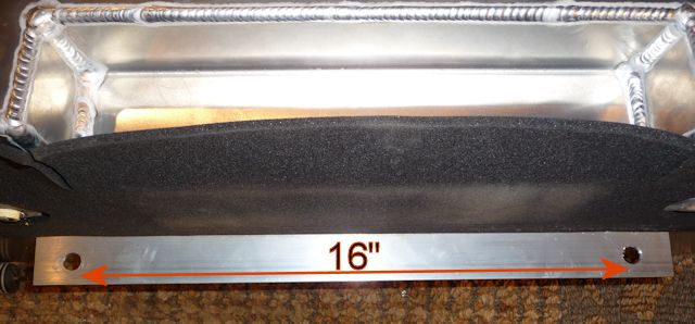
When you go to drill the holes, make sure
you support the mount with wood blocks. The
two holes should be 16" apart.... at least
they were on my car. |
 |
|
And that
completes the hard part..........locating
and drilling all the mounting holes. I
forgot the picture but the rubber washers
are used here too. |
 |
|
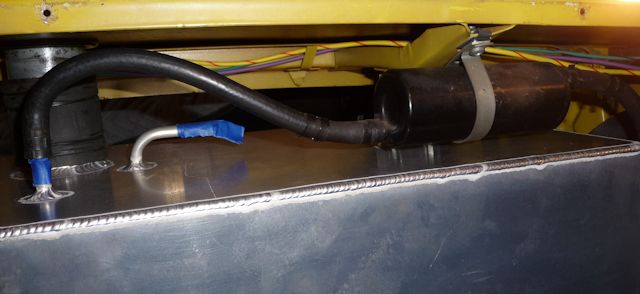
Here's the canister in its stock position
with the hose perfectly hitting the
fitting... no cutting required. |
 |
|
My filler hose always seemed too short to
me... as you can see.... so I bought a
longer piece that I'll use when I complete
the installation. |
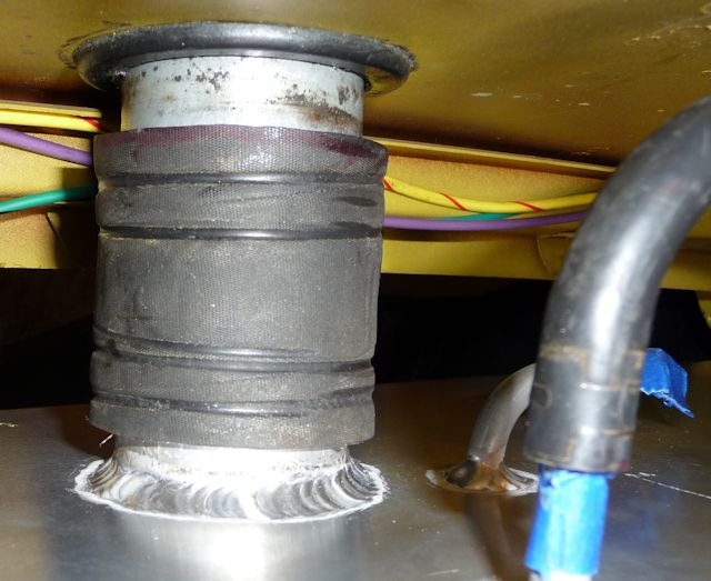 |
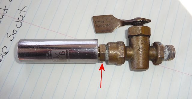
|
This is my 1/4" NPT fuel shut off valve from
NAPA Part #WH6828. The deep socket is
covering the hose barb but the easiest way
to install the valve is to slide the deep
socket over the hose barb to the "flats". |
 |
|
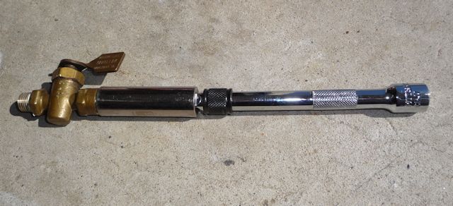
Add an extension and you can reach up and
screw it right on...........I used some
yellow Teflon tape rated for gas in the shut
off threads. |
 |
|
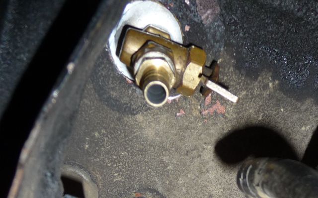
Just a test fit
but...... perfect! |
 |
| |