|
Critical
Measurements
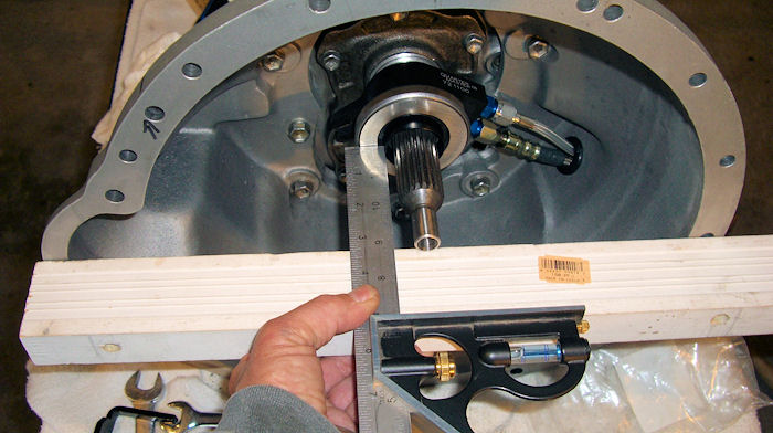
OK.....time to step back and
understand what these measurements mean. Let's start with
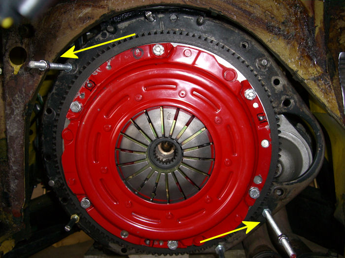
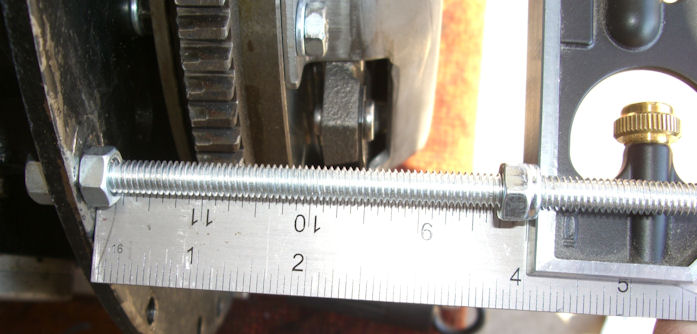
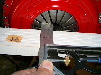
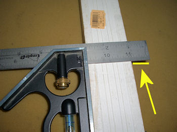
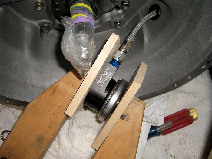
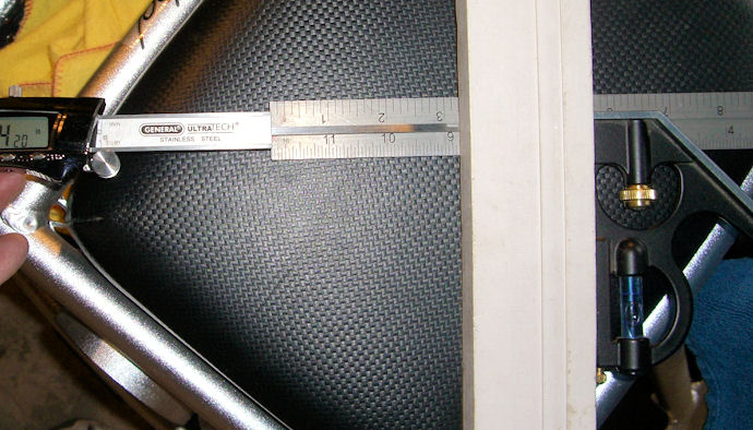
measurements "A". If you go back to setting
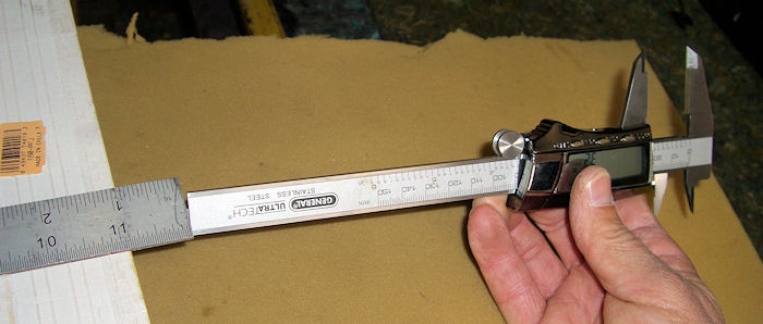
the measuring distance at 4" we used the caliper to
determine the distance from our straight edge to the pressure
plate fingers and called it measurement "A". Let's assume, for
simplicity sake that the distance was 0.50". Take that number and
subtract it from 4" so 4.00 - 0.50 = 3.50". Therefore 3.50" is
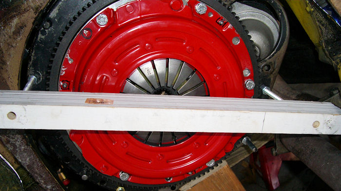
the final "A" measurement . The 1st goal here is to get the A & B
measurements to be the same.....or as close as we can get them.
In other words we want "B" to measure 3.50". Add or remove shims
as required to get the measurements equal or close to it. When
you have them "equal" it means that, if you were to install the
tranny, the t/o bearing would be touching the face of the
pressure plate. We don't want them touching so read the t/o
bearing instructions to see what spacing is required. My bearing
wanted a minimum of 0.125" and a maximum of 0.185" of separation
between the t/o bearing and the pressure plate fingers. So when
the tranny is installed, the t/o bearing is a minimum of 0.125"
and a maximum of 0.185" from the face of the pressure plate. I
had to remove a shim or two to obtain this spacing. I think my
final "B" measurement ended up being 3.64"....... 3.50" + 0.140"
= 3.64". The 0.140" fell right between the minimum and maximum
required.
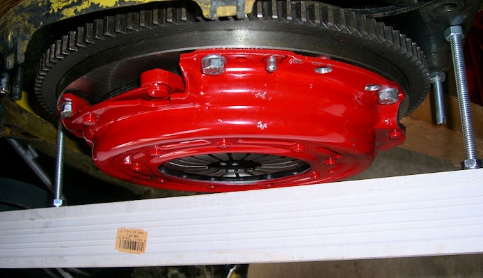
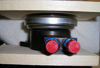
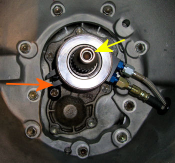
All that's left to do now is
install the bushing on the tranny nose and the bearing's
anti-spin stud.
Bushing (yellow arrow) takes some "persuasion"
to slide on the nose. Orange arrow points to
the bearing's anti-spin stud |
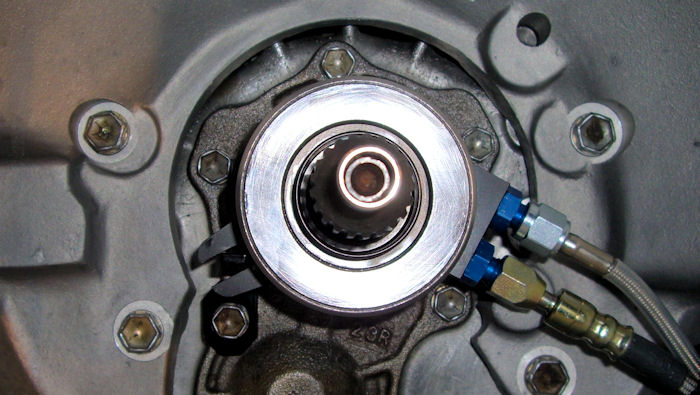
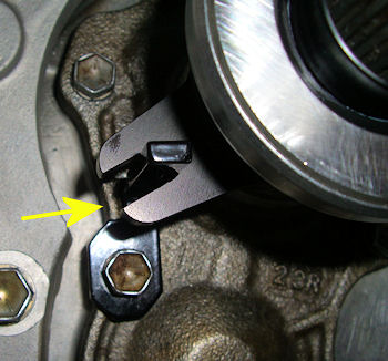
A
close up of the anti-spin stud |
 |
 |
Now we're
ready to attach the tranny to
the engine.
|