|
Injector Installation
The injectors
arrived along with all of the parts need for "fuel
delivery" but now it's time to put the injectors into
the adapters that Rick makes. Seeing as Rick has done a
good job of documenting this, I "stole" some pictures
and text from his web site!
 |
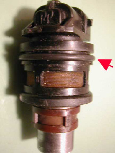
The injector pictured is a very common GM injector
used in various 4 cylinder GM cars from 1990 to 1995.

The red arrows indicate where o-rings seal against the injector.

Use a little automatic transmission fluid to lubricate
the o-rings. It is nearly impossible to insert the
injector without lubrication.
|
 |
An o-ring resides in this groove and is installed onto
the injector with lubrication. No sealant is used on
the o-rings. I used Dextron ATF  as the lube for both
sets of rings.
|
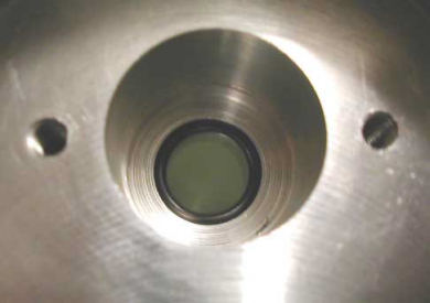 |
Looking down into the injector pocket you can see
that the small Black lower o-ring is in place. Be sure it
is down into it's pocket before attempting to insert
the injector. Lube this ring too!
|
Once the o-rings are in place
and lubricated, insert the injector with a twisting
motion. It should stop with the top edge just proud of
the aluminum pocket. Slip the half moon shaped retainer
in place (it doesn't matter which way it faces) and
tighten the two button head screws with a 1/8" allen
wrench. Before final tightening, align the injector in
whatever direction you desire.
The insert is held in
place in the Zenith Stromberg carbs by four stainless
steel philips head screws. No gasket between the insert
and the carb body is required. BE SURE THE INJECTOR
NOZZLE POINTS TOWARD THE ENGINE! The hose barb accepts a
5/16" hose and you should try to use fuel injection type
hose lamps. Typical fuel pressure is 12psi but some have
experimented with these injectors near thirty psi.
Needless to say keep an eye on the new installation for
possible fuel leaks.
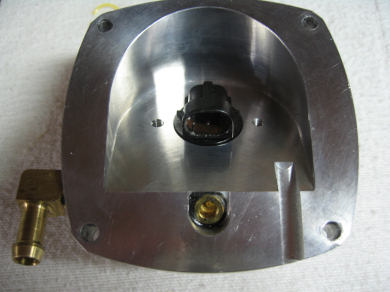
NOTE: Atop the insert is a
1/8" brass pipe plug that is used to cap off a drill
passage used during construction of the insert. The
internal passages within the insert are large and it is
doubtful they would ever become blocked but if need be,
the brass plug can be removed with a 3/16" allen wrench.
OK...so that's how Rick
instructs you to install the injectors into the
adapters. So let's see how it went for me when I had to
actually do it!
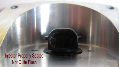
This is how the
injector should look when properly
seated....almost flush with adapter but not
quite.
I found it to be a 2 step twist/push to get
it seated.
The first step got it seated about 1/32"
above the
adapter and the second push got it this
point. |
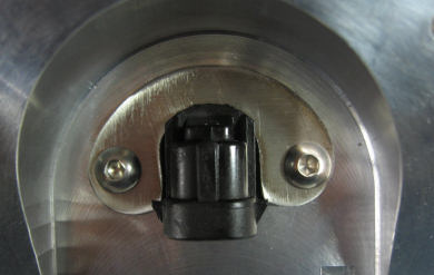
Here's the
business end. |
 |
 |
Here's a long
shot. That brass plug blocks a hole
needed for the milling process. |
The hold-down
bracket installed |
 |
 |
So far so good....nothing too
mechanically or automotively (a made up word)
challenging!
Next Up.....Gas Tank & Fuel
Lines
|