|
New
Differential Installation
Let me save you some time and
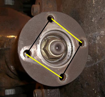
trouble right up front by pointing out that the 4 flange holes
for mounting to the driveshaft ARE NOT symmetrical i.e. a
perfect square. They are actually a rectangular shape so the
drive shaft flange will only mount up in 2 of 4 possible
combinations. Normally this wouldn't be a big deal but when
you've had the Nissan flange machined to match the Triumph
driveshaft flange you're left with 8 holes in the diff flange.
I know
it looks square but it isn't! The black
lines are about 3/8" longer then the yellow. |
Lots
of combinations here. The yellow are the
old holes and the pink are the new ones.
|
 |
 |
So..............BEFORE putting
your diff up on to the car, take your driveshaft flange and mate
it to the new flange and mark the holes with a dab of
paint......ideally one color for the short holes and another for
the long holes. You will be very happy that you did that. I had
planned on doing it but I had a senior moment and completely
forgot. As a result I tried to match the driveshaft flange to
the diff flange while both were in the car and I was working
alone. To make a long story short, I ended up removing the diff
and attaching the shaft out of the car.
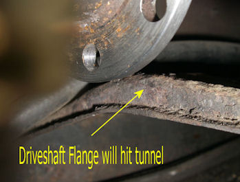
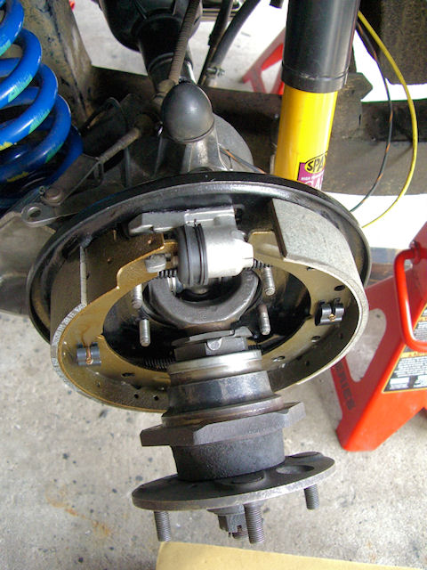
But first.........some diff
installation "issues" that I had to deal with. Using my diff
carrier, I was easily able to work the diff into position and
bolt it in place. Then I noticed that the flange didn't clear
the tunnel "tee shirt".......not good!
|
Definitely not enough
room to attach the driveshaft without hitting the
tunnel |
 |
 |
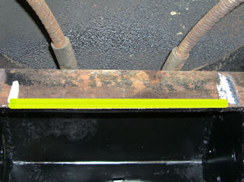
So what do you do?
Well..................you flatten the tunnel! Get the biggest C
Clamp you can find......this one has a 6" opening......along
with a big old crow bar and start turning! The irony is that
there are guys with brand new RATCO frames that are having the
exact same problem. Just the thought of using this technique on
a brand new $3300 frame makes me cringe.
| I was
able to pick up about 3/4" using this "technique". |
 |
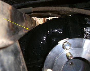
So that solved one problem but
then I spotted another. The top of the diff was hitting the
frame cross member that goes over the front mounting brackets.
So it looked like I'd be doing a little work with the angle
grinder.
| Hitting up
top |
Yellow
area gets ground down |
 |
 |
Once I was finished making my
"modifications" the diff was a perfect fit. Now all I needed to
do was measure the driveshaft length and get my driveshaft
shortened, welded and balanced. Remember that I'm doing the diff
upgrade along with the Toyota 5 speed conversion. Up until very
recently Herman's 5 speed instructions only called for
collapsing the driveshaft and using a locking collar that comes
with the 5 speed kit. Now Herman wants the driveshaft
shortened and welded to eliminate the slip in the driveshaft.
There will be a more detailed explanation of this in the 5 speed
section of my work. The end result was that
after talking to
FleetPride which is a national chain, I elected to have them build me a new solid
shaft that measured
26-5/8".
| The
new solid axle |
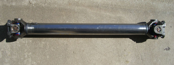 |
| and
all attached to the differential ready to be
installed. |
 |
It would have been much easier to
install the diff, then slide the driveshaft in and use a
telescopic magnet to guide the bolts into the
flange.............but, I didn't mark the flange holes as
mentioned at the beginning of this page. So I ended up working
this into place as a unit which isn't that difficult to do.
Next up was installing the axles
and bolting them to the diff. Make sure you read Richard's
directions on the use of the two springs that come with the kit.
| One
long, one short. |
The
short one goes in the driver's side axle |
 |
 |
Now, the only problem I had was
that Richard's instructions said to assemble the two halves and
slide them as a unit through the trailing arm. But there was no
way my rubber gaiter was going to fit through the trailing arm.
Maybe newer ones are more flexible and can be compressed but
mine wasn't about to fit. So on the driver side I loosely
attached the axle flange to the driveshaft flange and then slide
the other half of the axle through the trailing arm, eventually
lined up the splines and got it all together. On the passenger
side I did it basically the same way except I left the inner
half of the axle loose, got the splines together and then
attached it all to the driveshaft flange. Neither way was easier
or harder then the other way.
| Driver
side being assembled. |
 |
I did have one axle hub hole
binding on the trailing arm bolt so, following Richard's
directions, I went up one drill bit size and enlarged it.
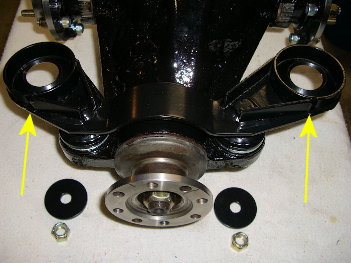
One last word of
advice...........leave the bolts to the Goodparts front mounting
bracket loose until you have it all connected to the driveshaft.
That way you have some free play to get everything lined up and
clear of any obstructions.
|
These
connect to the front mounting posts. Leave them
loose until everything is lined up. |
 |
Next Up........hooking up the 5
speed.
|